


Installing DCC in American Models Budd Co. Passenger Cars
by Michael Greene
Please be patient - there are 10 pictures on this page to load for viewing!
WHAT?!?!? Is the title right? Aren't DCC decoders for locomotives? YES and YES. But DCC decoders can be used many places. Earlier we used one to control an American Flyer operating accessory. Here's another use of them...
Budd Company Passenger Cars from American Models
When I saw the recently released S scale Budd Co. passenger cars from American Models running on our club layout, I was very impressed! American Models has raised the bar for S scale plastic models one more time. The detail work on exterior of the car, the interior detail, and the fully sprung passenger trucks all contributed to this new level of detail on S scale ready-to-run passenger cars. Shortly thereafter I acquired a four car painted but unlettered set for my layout. Note they are also available lettered for a number of roads, and you can choose between hi-rail or scale wheels. In hi-rail they are chromed cars, while the version with scale wheels comes painted with silver paint. The four car set includes a diner, coach, railway post office (RPO), and an observation car, with extra coaches available. The cars are factory supplied pre-wired with all wheel pickup and interior lighting, which makes this upgrade much easier.
For some time now I have thought about adding DCC decoders to passenger cars to provide extra features like dimmable lighting, control of other lighting, and perhaps in the future some sound and animation effects. When Lenz Electronik GmbH release their LE077XF ultra-small decoder last year, I knew that these decoders would be ideal for passenger cars. I placed a sizeable order with my dealer to get a quantity discount, and drive the price below $20 per decoder. The size of the decoder is: L:0.53" (13.4mm) x W:0.39" (9.9mm) x H:0.14"(3.3mm). Such a small size would be easy to hide in a passenger car. And with two independently controllable functions plus motor control, it provided a nice decoder to control the lights plus other items TBD.
One of the first steps in selecting a DCC decoder is to measure the current draw of the place it will be installed. The American Models Budd passenger car has a light board with three bulbs on it. On my test equipment it measured approximately 200mA at 14VDC. As an aside, if you're thinking about using these cars on a DCC layout without installing a DCC decoder, I would recommend that you do one of the following two things:
- replace the American Models supplied bulbs with smaller current draw bulbs such as the Miniatronics #18-016-10 (16VDC 30mA bulbs), and/or
- select and install an appropriate sized resistor in line with the light board.
The reason to do at least one of these is to reduce the current load placed on your DCC system, when the bulbs are started "cold". The inrush current on cold bulbs can be up to ten times the normal running current draw. This means that each car could place up to a 2A load on your DCC system at system startup or restart. If you had a string of 4 of these cars, that could add 8A of current draw at startup, a condition that would force some smaller DCC systems to report a short on the track. But that was an aside -- let's get back to the project at hand. For this project I will leave the American Models supplied bulbs installed, since each car will be under the control of a DCC decoder. Perhaps a future upgrade project will be to replace the bulbs with more prototypical passenger car lighting.
Installing a Lenz LE077XF in the Passenger Car
On first thought, you might think that I used either the F0 or F1 to control the lights. While that would have been possible it would have required a small amount of additional electronics. The functions on the LE077XF (like many other decoders) are only rated to provide 100mA of current. In order to use either F0 or F1, I would have needed to install some additional electronics, such that the function would actually control a relay that would provide track power to the lights when the function was turned on. This is certainly not a very difficult task, as we have used this same approach to provide power to smoke units in American Models Pacific locomotives when we have installed DCC. But using a function to control the lights would give me very limited control of the lights - either off or on at full intensity.
Instead I connected the light board to the motor wires on the decoder. The LE077XF is rated to provide 500mA of continuous motor current which is more than enough to run the lights without additional electronics. And this approach gives me complete control of dimming the lights -- from completely off to completely on, and 128 steps in between. In addition, using the motor leads for the lights leaves F0 and F1 free to control other effects if desired.
American Models has made access to the interior very easy. In
the next photo you'll see the bottom of the passenger car. Look for the four
screws, two next to each truck. Remove these and the shell can easily be removed.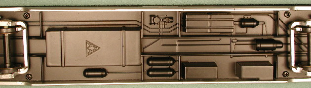
In the next photo you can see the car with the shell removed.
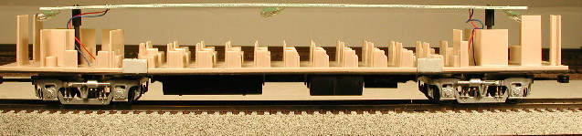
Notice that
there are three bulbs hanging below the light board. Also note the red and blue
wires at each end -- these connect the power pickups to the light board. Since
DCC decoders follow NMRA Recommended Practices for wiring color code (RP-9.1.1),
you need this table for correct color connections later in the installation:
|
|
NMRA |
American Models |
|
Right Rail Pickup |
red |
blue |
|
Left Rail Pickup |
black |
red |
Here's a close-up on the light board at one end: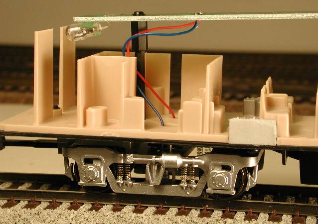
Our basic plan of attack for this installation is to:
- disconnect the pickups wires from both spots on the light board
- "hang" the decoder from the underneath of the light board away from any of the bulbs (the reason for this is that the light board is almost to the underside of the shell, and there is insufficient space to put the decoder on top of the light board.)
- connect the pickups from the trucks to the rail pickup wires on the decoder
- connect the light board to the motor wires on the decoder
- install any extra lights desired, and connect to F0 or F1
Most of the wiring will be done on top of the light board to
keep it out of view. In order to make the wiring a bit neater, I drilled a few
extra holes in the light board, carefully AVOIDING the traces on the board.
On the board near the front of the car, I drilled one pair of extra holes
as shown in the next picture: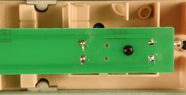
Then
I used my soldering iron to disconnected the power pickup wires from the light
board. Carefully keeping the colors on the same side as they were, I ran these
wires up through the new holes I had drilled. At the rear of the car, I drilled
TWO pair of extra holes as shown in the next photo.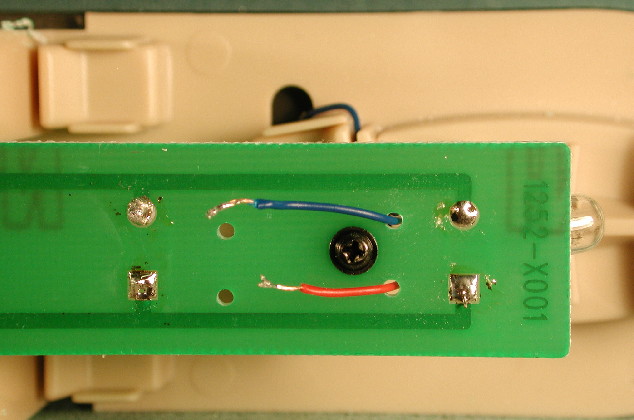
As you can see, in one pair of these I ran the power pickups, again carefully
keeping the colors on the same side they were on originally. The other set of
holes will be used for the rail pickup wires from the decoder. Now is a good
time to double check that once you have finished this, that both blue wires
are on the same side of the board. Than I spliced in some wire to make
the power pickup wires at the front of the car long enough to reach the rear.
Here's a
close-up. Note the heat shrink tubing over the solder joint, and the Scotch
tape holding the wires in place.
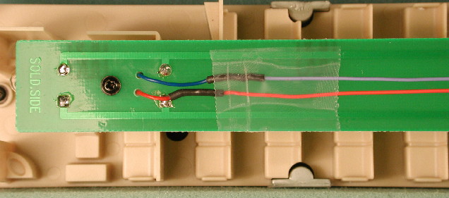
The next step is to "hang" the decoder. I used a very
small piece of 0.5" wide double stick foam tape to hold the decoder. Put
the foam tape on the micro-processor side of the decoder, since the other side
of the decoder will generate heat as current flows. The micro-processor
side is the side with the large chip. This next photo shows the decoder hanging
on the light board. Look to the right, behind the passengers.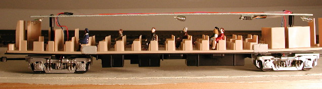
Once
you have the decoder in place, you now need to connect up the wires. I ran the
red and black wires from the decoder up through the other set of holes I previously
drilled in the light board. I cut the wires shorter (to approximately the length
needed), and then soldered the appropriate three wires together -- the
decoder's black wire and the two red wires from the American models pickups.
Then soldered the other three wires -- the red wire from the decoder, and the
two blue wires from the American Models power pickups. Don't forget to put a
piece of heat shrink tubing on the wire before soldering. Once the soldering
job is complete you can slide the heat shrink tubing in place and shrink it with
the warm part of your soldering iron.
Finally you need to connect the decoder's motor wires to the light board. I used the holes on the light board where the rear power pickups were originally connected. I cut the orange and gray wires on the decoder to the approximate length needed (don't leave a lot of extra as it will hang into the passenger compartment and be unsightly). Strip a small amount of insulation off of the end of each wire and tin the bare wire. Then using your soldering iron heat one of the holes where you removed the power pickups from the light board. While it is hot push the orange wire through from the underside. Repeat with the gray wire on the other hole. Note the orange wire should be connected to the whole on the same side of the light board as the American Models blue power pickup wires and the red decoder wire. And the gray wire on the opposite side.
Tip: I had one car that required cleaning the wheels really well with a wire
brush or fine sandpaper in order to get any pickup from the rails at all.
Once this is all done you're ready to test your installation.
Take the car to a DCC programming track. See if you can change the address.
I gave each of my passenger cars a unique four digit address, and when they
are running together in same train, I will actually consist them on the layout
so that all lighting in the cars is controlled together (except for any lights
which are connected to function wires). If you are unable to change the address,
you'll need to go back and troubleshoot your installation. If you were successful,
then you can proceed to finish up the installation. In the next photo you can
see that I used some additional Scotch tape to hold the wires in place on top
of the light board.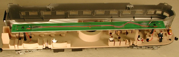
The
observation car also offers the opportunity to light and control independently
the red tail light. I connected the white and blue wires from the decoder to
a Miniatronics 16VDC 30mA bulb and placed it right next to the red lens in the
shell. I used electrical tape to hold it in place and keep that light from escaping
elsewhere into the cabin. ( Alittle better solution would be to place the bulb
in a short piece of brass tubing with the bulb sicking out next to the lens,
but I was running short on time.) Now F0 will turn that light on and off independently.
Finally to make sure that the F0 was not direction sensitive, I programmed CV51
to a value of 1.
Conclusion
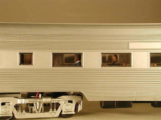
To finish the cars, I added some passengers using MTH figures.
Here you can see the figures installed before the shell is added, and in the
next photo you can see the passengers through the windows.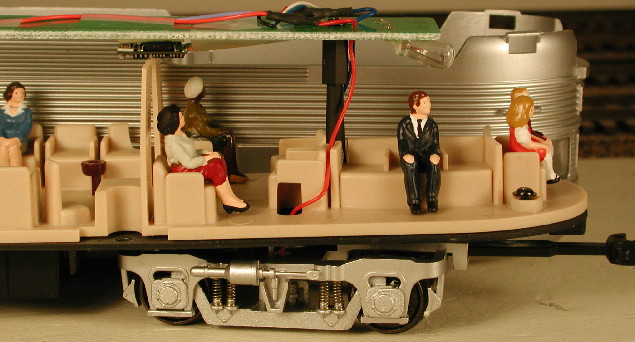
To date I have finished two of the four cars, and plan to complete the work in time to run them at a train show the middle of August 2001. I'll use my American Model Amtrak F40PH with working strobes or American Models 4-6-2 with sound, smoke and lights to pull them. I hope this information will make it easier for you if you are interested in installing DCC in your American Models Budd Co. passenger cars. Perhaps in the future I can upgrade the dining car to have a waiter moving up and down the aisle delivering food!
Good luck with your installation!
Michael
Copyright © 2002-2006, C. M. Greene. All rights reserved.
webmaster